Skip to content

Wiring Diagrams

Complete wiring reference for the IoT Toolkit.

Master Wiring Diagram

ESP32 Pinout Reference

DevKit V1 (30-pin) Layout

          EN          GPIO23    GPIO22    GPIO1     GPIO3     GPIO21    GPIO19    GPIO18    GPIO5     GPIO17    GPIO16    GPIO4     GPIO0     GPIO2     GPIO15    GPIO13    GPIO12    GPIO14    GPIO27    GPIO26    GPIO25    GPIO33    GPIO32    GPIO35    GPIO34    GPIO39    GPIO36    VCC       GND
           |            |         |         |         |         |         |         |         |         |         |         |         |         |         |         |         |         |         |         |         |         |         |         |         |         |         |         |         |
    [ESP32 DevKit Board]
           |            |         |         |         |         |         |         |         |         |         |         |         |         |         |         |         |         |         |         |         |         |         |         |         |         |         |         |         |         |
          RST          GPIO23    GPIO22    TX0       RX0       GPIO21    GPIO19    GPIO18    GPIO5     GPIO17    GPIO16    GPIO4     GPIO0     GPIO2     GPIO15    GPIO13    GPIO12    GPIO14    GPIO27    GPIO26    GPIO25    GPIO33    GPIO32    GPIO35    GPIO34    GPIO39    GPIO36    3.3V      GND

Complete System Wiring

Overview Diagram

                              +-------------------+
                              |     ESP32         |
                              |                   |
        +---------------------+ GPIO21 (SDA)      +---------------------+
        |                     | GPIO22 (SCL)      |                     |
        |                     | GPIO18 (SCK)      |                     |
        |                     | GPIO19 (MISO)     |                     |
        |                     | GPIO23 (MOSI)     |                     |
        |                     | GPIO5 (CS)          |                     |
        |                     | 3.3V / GND        |                     |
        |                     +-------------------+                     |
        |                                                               |
        |           I2C Bus                          SPI Bus            |
        +---------------+                          +----------+         |
        |               |                          |          |         |
   +----+----+    +-----+----+    +--------+   +---+--+   +--+---+      |
   | Temp    |    | Humidity |    | I2C    |   | TFT  |   |     |       |
   | Sensor  |    | Sensor   |    | Mux    |   | Disp |   |     |       |
   +---------+    +----------+    +--------+   +------+   +-----+       |
                                                                          |
   +---------+    +----------+    +--------+   +------+                    |
   | Vib     |    | Acoustic |    | Voice  |   | LCD  |                   |
   | Sensor  |    | Sensor   |    | Module |   | Disp |                   |
   +---------+    +----------+    +--------+   +------+                   |
                                                                          |
   +------------------+                                                   |
   | Camera Module    |                                                   |
   | (ESP32-CAM)      |                                                   |
   +------------------+                                                   |

Detailed Connections

I2C Bus (GPIO21=SDA, GPIO22=SCL)

Device SDA SCL VCC GND Notes
Temperature Sensor GPIO21 GPIO22 3.3V GND
Humidity Sensor GPIO21 GPIO22 3.3V GND
Vibration Sensor GPIO21 GPIO22 3.3V GND
Acoustic Sensor GPIO21 GPIO22 3.3V GND
LCD Display GPIO21 GPIO22 3.3V/5V GND I2C backpack
I2C Multiplexer GPIO21 GPIO22 3.3V GND TCA9548A
Voice Module GPIO21 GPIO22 3.3V/5V GND

SPI Bus (TFT Display)

TFT Pin ESP32 Pin Notes
VCC 3.3V Power
GND GND Ground
SCK GPIO18 SPI Clock
MISO GPIO19 SPI MISO
MOSI GPIO23 SPI MOSI
CS GPIO5 Chip Select
DC Data/Command
RST Reset
LED 3.3V Backlight (or PWM)

I2C Multiplexer Channels

TCA9548A Multiplexer
       |
       |-- SD0/SC0 --> [Channel 0 Device]
       |-- SD1/SC1 --> [Channel 1 Device]
       |-- SD2/SC2 --> [Channel 2 Device]
       |-- SD3/SC3 --> [Channel 3 Device]
       |-- SD4/SC4 --> [Channel 4 Device]
       |-- SD5/SC5 --> [Channel 5 Device]
       |-- SD6/SC6 --> [Channel 6 Device]
       |-- SD7/SC7 --> [Channel 7 Device]

Camera Module (ESP32-CAM)

ESP32-CAM uses dedicated pins. Connect separately:

Function GPIO Notes
Power 3.3V -
Ground GND -
U0TXD GPIO1 Serial TX
U0RXD GPIO3 Serial RX
Flash GPIO4 LED control
PSRAM GPIO16 External RAM
Camera Multiple Fixed assignment

Power Distribution

3.3V Rail

  • ESP32 (internal)
  • All I2C sensors
  • TFT display
  • I2C multiplexer
  • Voice module (if 3.3V)

5V Rail (if using 5V LCD)

  • LCD Display (with I2C backpack)
  • Voice module (if 5V)

Power Budget Estimate

Component Current Voltage
ESP32 (active) 120-250mA 3.3V
Temperature Sensor ~1mA 3.3V
Humidity Sensor ~1mA 3.3V
Vibration Sensor ~1-5mA 3.3V
Acoustic Sensor ~1mA 3.3V
LCD Display ~10mA 3.3V/5V
TFT Display ~50mA 3.3V
I2C Multiplexer ~1mA 3.3V
Voice Module ~20-50mA 3.3V/5V
Camera Module ~100mA 3.3V
Total ~300-500mA -
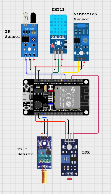
Breadboard Layout

Breadboard Layout (830 tie points)

[Top Power Rails]
Red (+):    3.3V from ESP32 --------------------------->
Blue (-):   GND  --------------------------------------->

[Component Row 1-10]
ESP32 DevKit (across center divider)

[Component Row 11-20]
I2C Multiplexer
Temperature Sensor
Humidity Sensor
Vibration Sensor
Acoustic Sensor

[Component Row 21-30]
LCD Display (I2C)
TFT Display (SPI)
Voice Module
Camera Module (separate or at end)

[Bottom Power Rails]
Red (+):    5V (if needed) ----------------------------->
Blue (-):   GND  --------------------------------------->
Color Purpose
Red 3.3V / 5V Power
Black Ground
Yellow I2C SDA
White I2C SCL
Blue SPI SCK
Green SPI MOSI
Orange SPI MISO
Purple SPI CS
Gray Other GPIO

Pull-up Resistors

I2C requires pull-up resistors on SDA and SCL:

  • 4.7kΩ recommended for 3.3V I2C
  • Many modules include pull-ups
  • Add external resistors if communication is unstable
3.3V ----[4.7kΩ]----+---- SDA (GPIO21)
                    |
3.3V ----[4.7kΩ]----+---- SCL (GPIO22)

Testing Connections

I2C Scanner

Upload I2C scanner to verify all I2C devices:

#include <Wire.h>

void setup() {
  Wire.begin();
  Serial.begin(115200);
  Serial.println("\nI2C Scanner");
}

void loop() {
  Serial.println("Scanning...");

  for (byte address = 1; address < 127; address++) {
    Wire.beginTransmission(address);
    if (Wire.endTransmission() == 0) {
      Serial.print("I2C device at 0x");
      if (address < 16) Serial.print("0");
      Serial.println(address, HEX);
    }
  }

  Serial.println("Done\n");
  delay(5000);
}

Troubleshooting

Issue Check
Device not detected Verify I2C address, check wiring, test with multimeter
Intermittent connection Check loose wires, add pull-up resistors
SPI display blank Verify CS pin, check initialization sequence
Brownouts Add capacitor (100μF) near power pins
I2C conflicts Use multiplexer, verify unique addresses

Next Steps