ESP32 Setup
The ESP32 is the heart of the IoT Toolkit - a powerful WiFi-enabled microcontroller that connects all sensors to the cloud.
Overview
The ESP32 provides: - Dual-core processor (up to 240MHz) - Built-in WiFi (802.11 b/g/n) - Bluetooth (optional) - Multiple GPIO pins - ADC, DAC, PWM, I2C, SPI, UART support
Specifications
| Feature | Specification |
|---|---|
| Processor | Dual-core Xtensa LX6 |
| Clock Speed | Up to 240MHz |
| RAM | 520KB SRAM |
| Flash | 4MB (typical) |
| WiFi | 802.11 b/g/n |
| GPIO | 34 programmable pins |
| ADC | 12-bit, 18 channels |
| DAC | 8-bit, 2 channels |
| Operating Voltage | 3.3V |
| Input Voltage | 5V (via USB) or 3.3V |
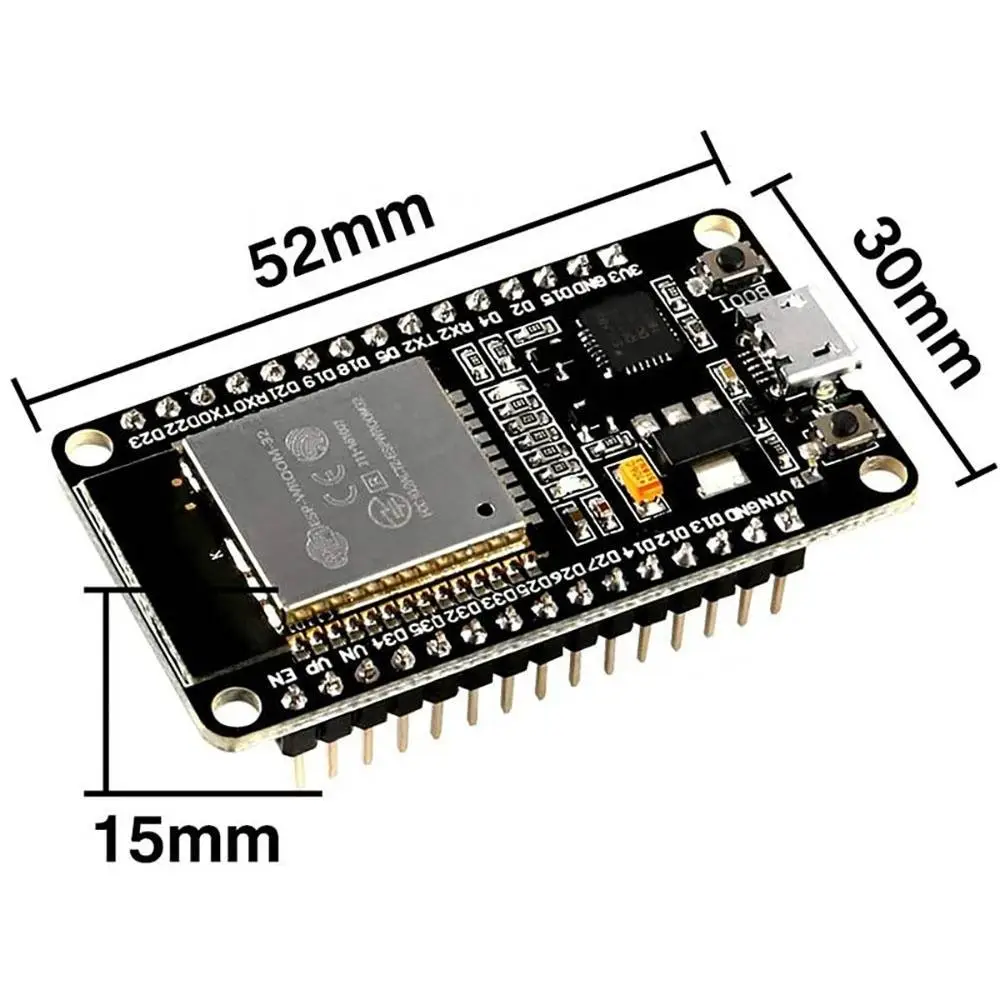
Pinout Diagram
          EN          GPIO23    GPIO22    GPIO1     GPIO3     GPIO21    GPIO19    GPIO18    GPIO5     GPIO17    GPIO16    GPIO4     GPIO0     GPIO2     GPIO15    GPIO13    GPIO12    GPIO14    GPIO27    GPIO26    GPIO25    GPIO33    GPIO32    GPIO35    GPIO34    GPIO39    GPIO36    VCC       GND
           |            |         |         |         |         |         |         |         |         |         |         |         |         |         |         |         |         |         |         |         |         |         |         |         |         |         |         |         |         |
    [ESP32 DevKit Board]
           |            |         |         |         |         |         |         |         |         |         |         |         |         |         |         |         |         |         |         |         |         |         |         |         |         |         |         |         |         |
          RST          GPIO23    GPIO22    TX0       RX0       GPIO21    GPIO19    GPIO18    GPIO5     GPIO17    GPIO16    GPIO4     GPIO0     GPIO2     GPIO15    GPIO13    GPIO12    GPIO14    GPIO27    GPIO26    GPIO25    GPIO33    GPIO32    GPIO35    GPIO34    GPIO39    GPIO36    3.3V      GND
Key Pin Assignments
| Pin | Function | Common Use |
|---|---|---|
| GPIO21 | I2C SDA | Default I2C data |
| GPIO22 | I2C SCL | Default I2C clock |
| GPIO18 | SPI SCK | SPI clock |
| GPIO19 | SPI MISO | SPI data in |
| GPIO23 | SPI MOSI | SPI data out |
| GPIO5 | SPI CS | SPI chip select |
| GPIO0 | Boot | Boot mode (don't pull low on boot) |
| GPIO2 | Boot | Boot mode (must be floating or pulled high) |
| TX0 (GPIO1) | UART TX | Serial output |
| RX0 (GPIO3) | UART RX | Serial input |
Arduino IDE Setup
1. Install ESP32 Board Support
Follow the Prerequisites guide to install ESP32 support in Arduino IDE.
2. Select Board Configuration
In Arduino IDE:
3. Serial Port Selection
Select the correct COM port:
4. Upload Settings
| Setting | Value | Description |
|---|---|---|
| Upload Speed | 921600 | Fast upload |
| CPU Frequency | 240MHz | Maximum speed |
| Flash Frequency | 80MHz | Flash access speed |
| Flash Mode | QIO | Quad I/O mode |
| Flash Size | 4MB | Standard flash size |
| Partition Scheme | Default 4MB | Partition layout |
First Sketch
Blink Test
Verify your ESP32 is working:
// ESP32 Blink Test
// LED is on GPIO2 for most ESP32 DevKits

#define LED_BUILTIN 2

void setup() {
  pinMode(LED_BUILTIN, OUTPUT);
  Serial.begin(115200);
  Serial.println("ESP32 starting...");
}

void loop() {
  digitalWrite(LED_BUILTIN, HIGH);
  Serial.println("LED ON");
  delay(1000);

  digitalWrite(LED_BUILTIN, LOW);
  Serial.println("LED OFF");
  delay(1000);
}
Expected Output
In Serial Monitor (115200 baud):
And the on-board LED should blink.
WiFi Connection Test
Test WiFi connectivity:
#include <WiFi.h>

const char* ssid = "YOUR_WIFI_SSID";
const char* password = "YOUR_WIFI_PASSWORD";

void setup() {
  Serial.begin(115200);

  Serial.print("Connecting to ");
  Serial.println(ssid);

  WiFi.begin(ssid, password);

  while (WiFi.status() != WL_CONNECTED) {
    delay(500);
    Serial.print(".");
  }

  Serial.println("");
  Serial.println("WiFi connected");
  Serial.println("IP address: ");
  Serial.println(WiFi.localIP());
}

void loop() {
  // Connection maintained automatically
}
Power Considerations
Power Supply Options
| Method | Voltage | Current | Use Case |
|---|---|---|---|
| USB | 5V | 500mA | Development |
| External 3.3V | 3.3V | 500mA+ | Production |
| LiPo Battery | 3.7V | Varies | Portable |
Power Consumption
| Mode | Current | Notes |
|---|---|---|
| Active (WiFi) | 120-250mA | Normal operation |
| Active (no WiFi) | 50-100mA | Processing only |
| Modem Sleep | 20mA | WiFi off, CPU on |
| Light Sleep | 2mA | CPU paused |
| Deep Sleep | 10μA | Wake on timer/GPIO |
Common GPIO Usage
This toolkit uses:
| GPIO | Purpose | Connected To |
|---|---|---|
| GPIO21 | I2C SDA | All I2C sensors |
| GPIO22 | I2C SCL | All I2C sensors |
| GPIO18 | SPI SCK | TFT display |
| GPIO19 | SPI MISO | TFT display |
| GPIO23 | SPI MOSI | TFT display |
| GPIO5 | SPI CS | TFT display |
Troubleshooting
| Issue | Solution |
|---|---|
| Upload fails | Hold BOOT button, press RESET, release BOOT |
| No serial output | Check baud rate (115200), verify TX/RX |
| GPIO not working | Verify pin is not input-only (GPIOs 34-39) |
| WiFi won't connect | Check credentials, verify 2.4GHz network |
| Brownouts | Increase power supply capacity |
Next Steps
Once ESP32 is working:
- Connect sensors
- Add displays
- Configure cloud connectivity
ESP32 Variants
This guide works with any ESP32-WROOM-32 based board. Other variants (ESP32-S2, ESP32-C3, ESP32-S3) may have different pinouts.